
 , Sven Laux2, Eric Bodden1, 3,
 Accepted 14 January 2021
Available Online 16 February 2021
- DOI
- https://doi.org/10.2991/jase.d.210205.001
- Keywords
- Architecture
Runtime Verification
Database
AUTOSAR
Cloud - Abstract
Analyzing runtime behavior as part of debugging complex component-based systems used in the vehicle industry is an important aspect of the integration process. It is a laborious task that involves many manual steps. One reason for this is that, as of today, the analysis is usually not performed on the architecture level, where the system has initially been designed. Instead, it relies on source code debugging or visualizing signals and events. With an ever-growing complexity of such systems, it becomes increasingly difficult to find errors that manifest at integration level, i.e., when the components interact with each other in a complex environment. Architectural Runtime Verification (ARV) is an approach specifically designed for the integrator—a generic way to analyze system behavior on architecture level using the principles of Runtime Verification. This paper draws on our initial publication. It provides further details and an evaluation of the ideas using a database hosted in the cloud.
- Copyright
- © 2021 The Authors. Published by Atlantis Press B.V.
- Open Access
- This is an open access article distributed under the CC BY-NC 4.0 license (http://creativecommons.org/licenses/by-nc/4.0/).
1. INTRODUCTION
Verification of control devices is an important aspect in many industries. Especially in the transportation industry, safety requirements and a highly distributed development process command manufacturers and suppliers to perform extensive testing. It therefore has been is an integral part of guidelines and standards, such as the ISO 26262 standard [1]. Figure 1 depicts the V-model of part 6: Product development at the software level.
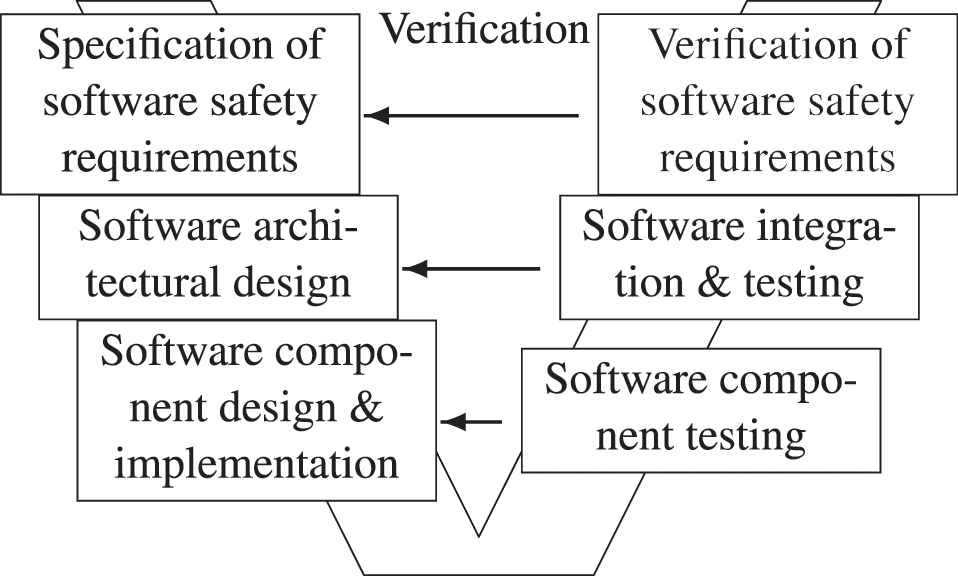
ISO 26262-6 development process [1].
The software of such devices is usually developed in a component-based fashion, where each component is first implemented and tested individually before being integrated.
The verification of integrated systems is difficult due to both, software architectures and hardware setups have become more distributed and heterogeneous. Methods such as model checking, which might be applicable to individual components, suffer from the state-explosion problem and thus cannot be used on integration level. Also, system specifications are often informally stated [2] prohibiting formal methods. Thus, the main verification method at integration level is simulation-based testing.
Whenever a test fails, developers must uncover the actual cause for the misbehavior. Given the complexity of an integrated system, this can be difficult. The actual defect is often not found where a violation or an undesired effect is observed. Furthermore, there can be other components participating in the test (e.g., plant models, other simulated controllers) that might contribute to the misbehavior [3].
Unfortunately, to our knowledge no publications exist that reveal how much this problem affects the development process of a complex integrated system, such as a car or an airplane. Such information is usually kept confidential. Generally, the domain of debugging on integration level is not a very common topic in the literature. There is material available that deals with the debugging of embedded real-time systems. Examples are the work of Thane and Sundmark et al., which covers the low-level technical aspects of accessing the runtime data, e.g., on how to minimize the impact on the system and achieve deterministic replay [4,5]. Like with many approaches, they consider a standard debugger to be used for the actual analysis. Also, they focus on the embedded system, whereas the interplay with other parts/components of the test setup is not in scope.
Some research in the field of integrated systems debugging has been conducted in other domains. For example, Østerlie and Wang analyzed the debugging process in open source software (OSS), more specifically in Gentoo Linux, using an ethnographic study [6]. Of course, it differs from how the integration is done in the transportation industry in that there is no (social) interaction and no collective sensemaking process with the customer, which plays an important role according to the study.
Thus, to learn about integration-related errors and bugs, we looked at some of our (customer) projects and interviewed developers from different OEMs that had been assigned the role of integrators. The following three examples should give the reader a broad idea of what kind of problems one might face on integration level when working with complex component-based systems.
The first real-life example that had been disclosed to us by a well-known car manufacturer was an issue with a side mirror that did not swing in properly (only half-way), when the ignition had been turned off. The side mirror electronic control unit (ECU) had been thoroughly tested and the behavior could not be reproduced when testing it individually. After a thorough investigation it was found that a complex interaction of several ECUs lead to a premature shutdown of the responsible side mirror controller so that it could not finish its task.
Another example was a sporadic spike in a control variable that represented a continuous signal. It appeared only when the software was integrated in the system and was not reproducible when testing the software individually. What was so confusing about this error was the fact that the spike did not seem to have an effect on the control loop and also seemed to appear randomly. Discontinuities like this usually indicate a sudden bit flip or a sensor problem, both of which do happen only very rarely. So this was unlikely the issue here. It took several “veteran” engineers a couple of weeks to find the actual cause. In this case, it was an unrelated software component that just happened to be integrated on the same microcontroller (something quite common in AUTOSAR architectures). The other software component defined a variable that coincidentally had the same name (compile symbol) as the one that exhibited the strange behavior. During the linking of the final software, they were both assigned the same memory regions. This resulted in one variable sporadically overwriting the other at runtime.
The third example originates from a past project, which was about the evaluation of a common tool-chain for designing AUTOSAR controllers for electric vehicles (cf. Ref. [7]). The control software would slowly start to oscillate under certain conditions, but only when the controller had been integrated in the architecture. The unit tests did not show this behavior. Although the system was comparably simple, it took us considerable time to find the culprit, which in this case was a sub-optimal scheduling sequence of tasks that resulted in dead time added to the control loop.
Such defects can only be uncovered when the system's behavior as a whole is taken into account. It requires knowledge of the system's architecture as well as expertise and experience in the debugging of such systems. A common systematic approach is to induce hypotheses about a possible cause from the observed behavior and then continuously refine it by testing predictions that result in further observations. This is commonly referred to as the scientific method in debugging [8]. It has been proposed as early as the nineties by Akari et al. They stated that a debugging tool should provide a “facility of theorem proving or at least proof-checking to help programmers verify their hypotheses about programs and errors” [9]. It is our understanding that as of today there is no such thing in the area of debugging at the integration level. The whole part of verifying/refuting hypotheses or, more precisely, the behavioral predictions inferred thereof, is still a manual process. It mainly involves signal plotting and source code analysis (the classical step-by-step debugging). However, a developer must have a deep understanding of the integrated system to find a good spot for a break point. Even if the source code is available, which is not always the case due to IP protection, it may originate from different sources or might even be generated. Recent studies by Tiarks and Röhm found that understanding somebody else's code is one of the main problems in debugging [10]. In case of a real-time simulation, source code debugging is often not even an option. Also, it is not feasible to plot and analyze every individual signal. Selecting a new signal that has not been recorded previously or starting at a different break point requires to rerun the test. This makes the whole process time-consuming and tedious.
As a result, we are working on Architectural Runtime Verification (ARV)—a new approach that allows the formal analysis of the runtime behavior of an integrated system on architecture level. Like Thane and Sundmark, it assumes that data is recorded. This means that a user can verify/refute hypotheses after the testing is over to find the root cause for its failure. However, ARV goes even a step further by allowing to analyze multiple test runs at the same time. It boroughs ideas of a common technique used to verify the behavior of (software) components at runtime, which is called Runtime Verification (RV). The goal is to give a better understanding of the system behavior as a whole. Also, ARV could serve as a starting point for the traditional approaches, e.g., to decide which signals might be worth plotting or to find a good spot to set a break point in the code, which according to Tjarks and Röhm would already be an improvement [10].
This paper is an extended version of our initial work [11]. It extends on the original contributions:
a requirements analysis for a framework that allows RV to be applied on architecture level (Section 4)
a domain-independent model that augments the structure of a generic architecture with runtime information (Sections 5.1 and 5.2)
a way to formally state assumptions1 about the temporal behavior (Section 5.3)
a way to verify the assumptions using the RV monitor paradigm applied to a database, without having to query every single event (Section 5.4)
The paper is further structured as follows: The next section explains the main concepts of RV. Section 3 introduces an illustrating running example. After that, Section 4 presents a requirements analysis that forms the basis for the actual approach presented in Section 5. Sections 6 and 7 describe how we evaluated ARV using the running ex ample and Section 8 presents related work. The paper concludes with a brief outlook in Section 9.
2. ABOUT RV AND LINEAR TEMPORAL LOGIC
The information on the system behavior that is available at integration level is often limited, because components may be delivered in binary form. From an integrators' perspective, they are nothing but black boxes with hidden internals [12]. Hence, a complete model of the possible states rarely exists. Such black-box systems cannot be verified using formal verification techniques, such as Model Checking, but instead must be executed to test their behavior. Thereby, also the environment in which the components are finally integrated is considered for which otherwise again only insufficient information might be available [13]. RV is a technique that focuses on a concrete execution of a system rather than checking its model formally. Falcone et al. define RV as a “dynamic analysis method aiming at checking whether a run of the system under scrutiny satisfies a given correctness property” [14].
Basic concepts of RV are presented in the surveys by Leucker et Schallhart [13] and Falcone et al. [14] One central concept is that RV only requires formal properties as input for the verification. A model of the component's internal behavior is not required. This works by first automatically translating a given property into a monitor (monitor synthesis), which then observes the system's execution in a second step called monitoring. Here, the monitor consumes events produced by the system and outputs a verdict reflecting the satisfaction of the property.
In RV it is common that the monitoring is performed at runtime, i.e., online, by observing the trace of events produced by a current execution of the system. Often there is a dedicated component that performs the RV and becomes a part of the system itself. This makes it possible to react in case some misbehavior was detected. However, the overhead on the system in terms of response time and memory footprint must be kept minimal as other wise the system's behavior may be changed [15]. Alternatively, RV can be performed offline based on a previous execution whose trace was recorded and stored in a log.
In order to observe events, the system needs to be instrumented so that it generates events that can be fed to the monitor. Instrumentation is therefore a crucial part for RV frameworks. However, this implies dependencies on the system under scrutiny due to the used instrumentation approach. Falcone et al. [14] consequently do not include instrumentation in their definition of a RV system, but define such a system as consisting of a domain of possible verdicts, a set of possible events, a set of possible properties, and a method for generating monitors from properties.
In many RV approaches, it is common to specify the properties using Linear Temporal Logic (LTL) or a timed variant [16,17]. LTL is a formalism presented by Pnueli [18] that treats time in a linear way, i.e., for every state of the system there is exactly one next state. This characteristic enables the automatic generation of a finite-state machine (FSM) that forms the monitor. In addition to the logical operators and (
3. RUNNING EXAMPLE
This section presents a simplified example architecture of an automotive indicator system that we use to explain and evaluate the approach. It has been chosen mainly, because it is is sufficiently complex, i.e., contains different types of components and interfaces, while at the same time being easy to understand. It can be found in the SystemDesk2 modeling tutorial [19] and is depicted in Figure 2. It is particularly useful to illustrate the main concepts of AUTOSAR3, which offers a standardized component-based architecture description that involves different layers [20].
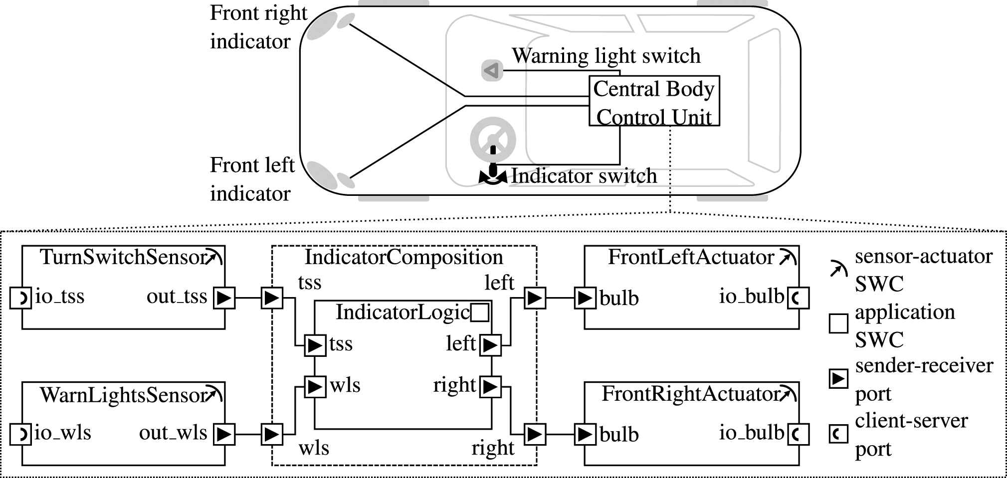
Simple AUTOSAR indicator example.
For simplicity reasons, it only includes the front left and front right direction indicators. The general functionality of such a system should be familiar. The front left/right indicator is triggered by an indicator switch. A hazard warning light switch triggers both direction indicators simultaneously. Corresponding sensors measure the current status of the switches and actuators are used to turn on/off the direction indicator lamps.
Assume that there is a failed test which involves checking that the warning light switch indeed triggers the indicators. Usually, such a test consists of many individual test steps in a sequence which set or check certain values/variables. In this case, it could be a sequence that (1) activates the warning light switch, (2) waits 200 ms (3) checks the left and the right indicator. When one of these individual steps fails (e.g., step 3), the test fails. The first task would be to find out what actually went wrong and then develop a hypothesis of the actual defect. Thus, an integrator would probably want to check the following assumptions about the behavior of the system:
A1 The warning light switch is pressed (anytime).
A2 The runnable of the IndicatorLogic component is invoked (anytime).
A3 The indicators are always activated within 200ms after the warning light switch has been pressed.
A3 is a good candidate for an analysis on architecture level as it involves different components and a real-time constrain.
4. REQUIREMENTS ANALYSIS
ARV's concept is based on a requirements analysis that we conducted in advance. The main requirements and design-goals are presented hereafter.
4.1. The Architecture Model
One requirement is that ARV should be usable beyond domain boundaries. This accommodates the heterogeneity of test setups. They are often composed of components from different domains, which themselves might be architectures. For example, on the highest level, there are components representing the controller (the system under test) and some representing the environment.
The latter is usually composed out of single-component models, e.g., Functional Mockup Units (FMUs [21]). In the automotive industry, the controller can be AUTOSAR-based, which means that it forms an architecture on its own. AUTOSAR features some unique architectural elements like “Runnable Entities” that wrap the behavioral code and are mapped to tasks of the operating system. Other domains can have custom descriptions that are created using, e.g., the Architecture Analysis & Design Language (AADL [22]). From this it follows that ARV's underlying architecture model must be very generic with the capability to represent hierarchies.
4.2. Recording Runtime Data
Another goal of an ARV framework is to allow users to confirm their assumptions about the runtime behavior without having to repeat the test. Furthermore, the approach should also be applicable in real-time simulation scenarios. Here, it is not possible to bring the simulation system to a halt for inspection without loosing reproducibility [5]. Therefore, the runtime information must be recorded.
Recording or logging simulation data has been done since the beginning of simulation-based testing of electronic control devices. From an engineer's view, runtime information mainly comprises signal curves. Looking from the software perspective, these signals are just changes in variables over time. At integration level, this implies an event-discrete nature of the system under scrutiny. Thus, every variable change can be seen as an event. Every such event has a timestamp, which implies a temporal relation to other events. However, depending on the resolution of the measurement, a timestamp is not necessarily unique. This means that the order in which events are recorded must be preserved.
In the past, only signals that were deemed significant for later analysis were recorded (often in a limited time frame to reduce the amount of data). However, to have a complete picture of the system's behavior, it is required to collect the runtime data from all (or at least most) of the involved components. Fortunately, there is a trend in the industry to record more extensively—a consequence of technological advancements in the area of real-time data logging, generally more affordable storage solutions and the advent of big data. There are even RV approaches that are based on the assumption that log information is available anyhow [23,24].
It can be argued that even with today's high capacity storage solutions, it would be infeasible to log every instruction and all changes in every local variable for hundreds of different configurations and tests. However, ARV only requires runtime information related to the architecture and not every single variable inside of a component. This means that the amount of data that needs to be recorded depends on the granularity of the architecture model. A less fine-granular model means less runtime data, while a more fine-granular model offers more insight, but also requires more runtime data.
4.3. Formulating Assumptions
In order to confirm or reject assumptions about the system's behavior, they must first be formalized based on the architectural elements. These “correctness properties” then form the base for the monitor synthesis and can then be evaluated automatically.
Two main aspects must be considered here: First, it must be possible to specify simple statements/assertions about the current state and second, it must be possible to specify temporal relations. The formalized simple statements are called atomic propositions and form the building blocks for more complex queries, where they are combined using logical operators. An example is A1 of the running example that the warning light switch is pressed, i.e., the input “io_wls” of the “WarnLightsSensor” component is 1. However, it is insufficient to just consider values of ports. The integrator also wants to know if and when a component was active, i.e., when its code was executed. This is important because a component not executing when anticipated, or doing so unexpectedly, is a common problem at integration level. An example is A2 that a runnable is invoked. To be clear, this does not include any aspects about the internal behavior of the component.
Regarding the temporal relations, it must be possible to state that a proposition holds a certain num ber of milliseconds before or after another proposition. This is important, because many behavioral anomalies on integration level are due to an unexpected sequence of events, such as the ones described in the introduction.
4.4. Accessing the Data
In spite of the fact that the granularity of the runtime data is limited to what is required for the architecture, one can assume that it will still be a significant amount of data. The framework must be able to handle those amounts storage-wise. Furthermore, it should be possible for a user to test assumptions about the behavior of a system in multiple executions. This gives a higher chance that the assumption is rejected, which helps to uncover false assumptions and at the same time increases assurance in an assumption that has not been rejected. However, this means that the monitor may need to process huge amounts of data.
As a result, the framework should separate the act of testing the assumptions from the data processing (separation of concerns). It must be noted that this is arguably more a design-goal than a requirement. It ensures that a client does not need to have all runtime data stored locally, nor should it be required to download or process it. Instead, it must be possible to interface the framework with state-of-the-art storage technologies, such as database management systems (DBMS) and cloud storage. This also ensures that there are no special hardware requirements regarding the client devices. Engineers increasingly expect to be able to work with tablets or even smartphones. Heavy processing and data transfer drains the battery on any portable device and should therefore be offloaded to the storage engine.
To some extend, a separation is already inherent in the RV monitor paradigm. However, as mentioned in Section 2, traditional RV approaches implement it as FSM, which processes every single event in a linear fashion. One RV approach that does this is called LARVA (see Section 8.6 and Ref. [24]). It uses a database to store and replay the events one by one. In contrast to that, a goal of ARV is to synthesize the monitor in a way that it uses the full potential of a DBMS, e.g., by the use of composed queries.
5. ARV CONCEPT
The fundamental idea of ARV is to utilize the RV Monitor paradigm to verify assumptions about the runtime of architecture elements. Consider assumption A3 from Section 3. To verify it, a user would need to check if any activation (i.e, a value change from 0 to 1) of port “io_wls” always yields the activation of both “io bulb” ports within 200ms. ARV lets a user formulate this inquiry, synthesizes an RV monitor and applies it to the runtime data.
For this to work, architectural elements have to be associated with “their” runtime data. Section 4.1 requires that ARV supports different architectural models with different runtime information. ARV accomplishes this through a generic domain-independent model, which can represent the structure and runtime of any domain-specific component-based architecture. This way, the same monitor can be applied to all data sets. It requires a Domain Adapter that transforms the domain-specific structure and runtime data into ARV's domain-independent model. The Domain Adapter must be supplied by a domain expert who knows both models. This allows to handle heterogeneous systems that consist of various kinds of architectures and run-time data. To support a new architecture description, it is sufficient to create a suitable Domain Adapter.
The translated domain-independent data is stored in a database. However, a user might still want to formulate in a domain-specific way. Therefore, the properties must also be translated by the Domain Adapter. if users are not familiar with the domain specifics, they can always use the domain-independent model for their inquiries. In the context of RV of component-based systems, this is a novel idea that none of the investigated approaches (see Section 8) has considered so far.
Figure 3 shows an overview of the approach. One can see the interaction between data acquisition (Logging) in the lower and Monitoring in the upper part. The following sections provide some further details regarding the concrete model and how the RV monitor is synthesized.
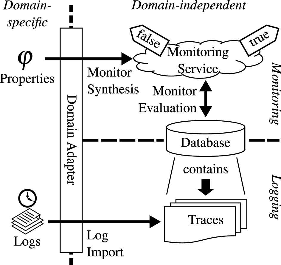
Overview of the main approach.
5.1. Representing Structure
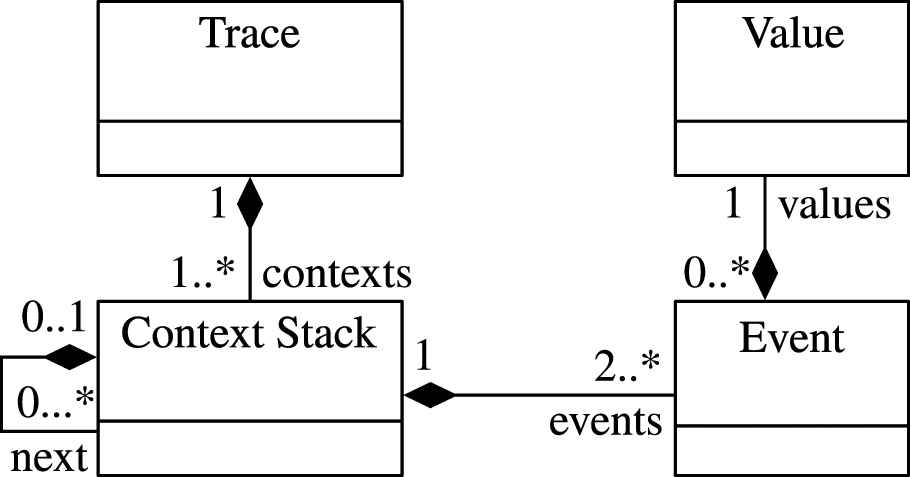
Designing a domain-independent model that sufficiently can represent any architecture is not trivial. It is a balancing act between having a simple and thus easy to handle model and crafting one that is capable of representing distinctive features of individual models like AUTOSAR. The domain-independent model that ARV uses to represent structure has been designed to resemble what can be considered a common ground for any component-based architecture in a simulation-based test environment. It can be seen in Figure 4.
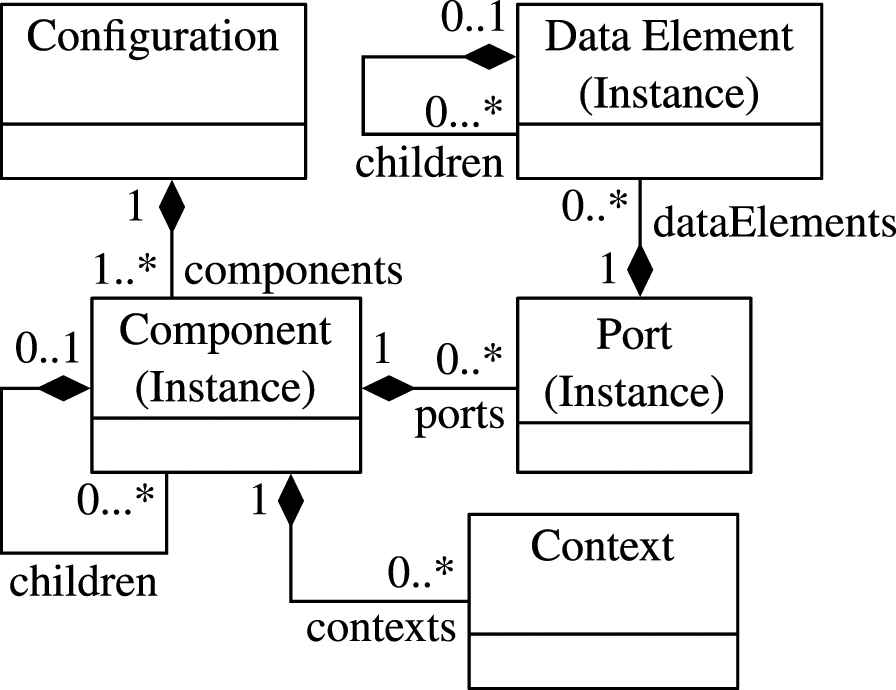
The structural model.
We could not find an existing model that was better suited and comparably simple. However, it should be regarded as a first step.
The “root” element is the Configuration that forms the container of one instantiated system. It may be composed of one or more components. A Component may contain other components (children), which makes it a composite component. A Port is an interaction point between components. The Data Element describes the actual data that is transmitted via the port. It can be nested to allow for complex data types (e.g., structs).
Components, Ports and Data Elements are actually instances of their respective type. This is in line with many component-based architectures and allows to reuse the component types. Also, verifying propositions regarding a component type has a much wider scope compared to that of one instance.
If the architecture in question has other element types that are relevant for runtime analysis, they will have to be mapped on those three just described. However, each of ARV's domain-independent model elements retains references to its domain-specific counterpart. This is required (1) to translate domain-specific properties into domain-independent ones that can be processed by the monitor and (2) to translate the domain-independent results back into domain-specific ones for inspection.
Finally, ARV adds another class named Context (short for Execution Context) to this model. It cannot be found in common architectures. The name relates to the programming domain, where every function or statement is executed within a designated context (e.g., scope, stack frame, thread, task). Similarly, every component can have several (execution) contexts, because its execution can be triggered from different places. A prominent example is again AUTOSAR, where the component's code may be executed in the context of different AUTOSAR Runnable Entities, which in turn are executed by different tasks. Furthermore, the Context also holds information about the execution state of a component, which is explained in the next section. If such information were to be added to the component directly, they could not have several execution contexts at the same time. Using a designated class circumvents this problem and furthermore keeps the domain-independent structural model clean and separated from the runtime aspects.
5.2. Representing Runtime Behavior
A monitor in RV processes runtime events, i.e., every new Event induces a new runtime state, which a monitor checks for certain conditions. ARV is no different in that regard, with the exception that it solely relies on a history of recorded events (trace). Its runtime model is depicted in Figure 5.
The behavioral model.
Besides the contexts, the Trace class at the top additionally contains all meta-information regarding the recording. One example is the simulation start time, which is the reference for the relative timestamps of the Events. Every Event relates to a structural element. This relation is realized through the Context class, which has been introduced in the previous section. ARV's runtime model supports nested contexts, i.e., contexts that are executed in (parent) contexts forming a ContextStack. This allows to reproduce causal relations between the execution of components.
There are two types of events: (1) those that relate to a signal transmission between ports, which induces a Value change at a port and (2) events that relate to the execution state of a Component in a particular Context. In its simplest form, the state can be either running or suspended, meaning the component's code gets executed or not. A change of the execution state relates to either a start or terminate event. Usually, the start event occurs when a function is called and the terminate event when it returns.
Of course, such events and states can only be tracked if the architecture supports it and if there is some means to generate the required logs (see bottom half of Figure 3). However, ARV will still be usable if this information is not available.
For a complex architecture standard like AUTOSAR, which includes a multitasking capable operating system, two states are insufficient. Here, a task has a more complex state machine. Basic tasks have a further state ready and extended tasks have an additional state waiting. More details regarding task scheduling of real-time systems can be found in the OSEK/VDX standard (see Ref. [25]). ARV must consider the waiting state and its transitions wait and resume, because they can be good indicators for resource deadlocks. The ready state on the other hand, is not considered by ARV. The ready state means that a task is prepared to run by the OS, but cannot, e.g., due to a task with a higher priority. On architecture level, i.e., from the perspective of the component, this state is not visible, because it is not a state of its execution context, but a state internal to the OS. This is also why on architecture level, this state is negligible. For this reason, ARV uses a state machine that contains only the states running, suspended and waiting, which can be seen in Figure 6.
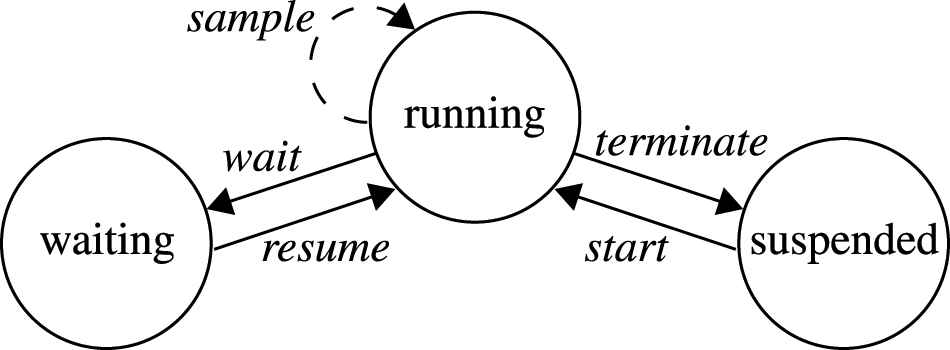
The state machine of Context.
5.3. Verifying Properties
Following the requirements from Section 4.3, ARV distinguishes two types of atomic propositions. First, state propositions can refer either to one of the previously defined states of a component's Context (see Figure 5) or to the current value of a data element at a port. Values can be compared to other values for (in-)equality. In a formal language, this can be expressed using standard operators =, ≠, <, ≤, > and ≥. The second type of atomic proposition is the event proposition. It incorporates information about the current event in a specific Context, i.e., start, terminate, wait, resume, or sample.
To specify temporal and logical relations between those atomic propositions (cf. Section 4.3), they must be combined using, e.g., a property specification language. There are different languages available that each have their own benefits and drawbacks. However, as stated in Section 2, LTL is a common means for specification in RV. Furthermore, LTL has the advantage that several timed extensions exist that take real-time properties into account. Because of this and its familiarity, we have chosen LTL as base for the specification language in ARV. Thus, it supports the standard LTL operators finally, until, and globally. We added the bounded interval syntax and semantics found in the Metric Interval Temporal Logic (MITL), which was presented by Alur and Feder in Ref. [26]. This allows to specify real-time constraints. Furthermore, the language supports the common logical operators not, and, or and implies.
5.4. Monitor Synthesis
The RV paradigm requires that a formal property
ARV performs a bottom-up monitor synthesis, where the formal properties are processed by a visitor that traverses the parse tree. This is similar to the approach by Maler et Nickovic [27], except that ARV processes discrete events instead of continuous signals. The result is a database query that returns the events in
Mapping the language operators presented in the previous section to the corresponding database query is straight forward for the logical operators, but requires some effort for the temporal operators. The former can be realized using set operations, such as union or intersect. For the latter, we briefly explain the general approach exemplarily for the finally operator, which is just a special case of the until operator, but easier to illustrate.
Let
In general,
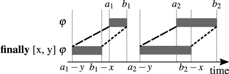
Finally operator applied to a set of events.
A naive approach is to query for each event in
6. EVALUATION OF IMPLEMENTABILITY
We have implemented a prototype and evaluated it using the example presented in Section 3. The first step was to create the necessary AUTOSAR-Domain Adapter as presented in the previous section. It consists of three parts: (1) a configuration adapter to insert concrete system configurations, (2) a log adapter to insert corresponding traces, and (3) a property adapter that allows the systems integrator to specify AUTOSAR-specific properties. Table 1 contains the mapping of AUTOSAR elements (table cells) to ARV's domain-independent structural model (table heading) and Table 2 the mapping of AUTOSAR-specific runtime data to the domain-independent events.
| COMPONENT | PORT(S) | CONTEXT(S) |
|---|---|---|
| System | - | - |
| ECU | Com | Task(s) |
| SWC | RPort(s), PPort(s), PRPort(s), IRV | Runnable(s) |
ECU, electronic control unit; ARV, architectural runtime verification.
Mapping of AUTOSAR to ARV's structural model.
| CATEGORY | AUTOSAR EVENT | ARV EVENT |
|---|---|---|
| API Call Begin | set | |
| RTE | API Call Return | set/get |
| Signal Transmission | set | |
| Signal Reception | get | |
| COM | Signal Invalidation | sample |
| Signal Grp. Invalid. | sample | |
| Com Callback | sample | |
| Task Activate | sample | |
| Task Dispatch | start | |
| OS | Task Termination | terminate |
| Set OS Event | sample | |
| Wait OS Event | wait | |
| Received OS Event | resume | |
| Invocation | start | |
| Runnable | Termination | terminate |
RTE, Runtime Environment.
Mapping of the runtime data.
We obtained the runtime data using a dedicated logging mechanism that we had added to the simulation platform.4 It uses a feature of the AUTOSAR Runtime Environment (RTE) that allows to hook in callbacks. By applying the respective adapters, the AUTOSAR-specific runtime data has been translated into its domain-independent form and stored into a database.
The final step of the evaluation was to formulate the actual assumption and let ARV process it. We have used ANother Tool for Language Recognition (ANTLR)5 to define the concrete grammar for the language and to generate a corresponding parser.
Listing 1 exemplarily shows how A3 can be formulated.
Listing 1: ARV timed LTL grammar example
globally (
(DATA_ELEMENT@“WarnLightsSensor/out_wls/value” == 0 and finally [0, 10]
DATA_ELEMENT@“WarnLightsSensor/out_wls/value” == 1)
implies finally [0, 200] (
DATA_ELEMENT@“FrontLeftActuator/bulb/value” == 1 and
DATA_ELEMENT@“FrontRightActuator/bulb/value” == 1));
It can be seen that the current language has its shortcomings. The value change from 0 to 1 must be formulated using an expression that involves finally with a one-cycle interval. This is cumbersome and a dedicated operator would be preferable, which is considered future work.
For each node, the parser creates a database query, but instead of generating SQL directly, ARV's implementation uses Microsoft's Entity Framework6 (EF) in order to abstract the concrete DBMS. This allowed us to test the implementation with different databases, including SQLite,7 Mari-aDB8 and Azure SQL Database.9
Furthermore, EF provides a Language Integrated Query (LINQ)10 interface. It allows to compose queries that defer the actual database access until a concrete event is requested (e.g., by querying the first or last element of a selected set). In theory, this means that the whole, or at least big parts of the parse tree can be composed into one single query. It is also in line with the RV paradigm that a monitor can be synthesized once and then applied to multiple traces of the same structural elements.
However, using EF does not only have benefits. When implementing the LTL operators we noticed that it is very difficult—if not impossible—to synthesize one composed query of an LTL expression that does not require EF to download intermediate results from the database. Arguably, one reason for this is that the data model is probably too simple. For example, it does not provide any direct way to get the related events of a data element, which leads to complex LINQ expressions. But the actual problem is that EF lacks support for many of the LINQ methods.11 Also, certain composed queries cannot be executed on the database, but need to be processed locally. This makes an implementation difficult, because one must either resort to a for-loop, which might end up downloading lots of data, or use a complex query involving multiple expensive joins.
It is also not trivial to have parts of the query run in parallel to improve the performance of the query, as the database context can only be accessed by one thread. An application would have to open a new database connection.
In addition to the unsupported LINQ methods, we have observed runtime-exceptions, syntax errors regarding the generated SQL query or even infinite loops when executing them depending on the back-end (e.g., MySQL, SQLiite, Microsoft SQL…). Furthermore, not every backend supports the same features and EF core, which is the platform independent version of EF, behaved very differently for some queries.
To summarize, it seems that EF might not be ideal when the LINQ expressions are complex to the level that is imposed by our monitor synthesis. However, we need to do some more research to make a definite statement.
For the graphical user interface we implemented a simple WPF12 front-end depicted in Figure 8.
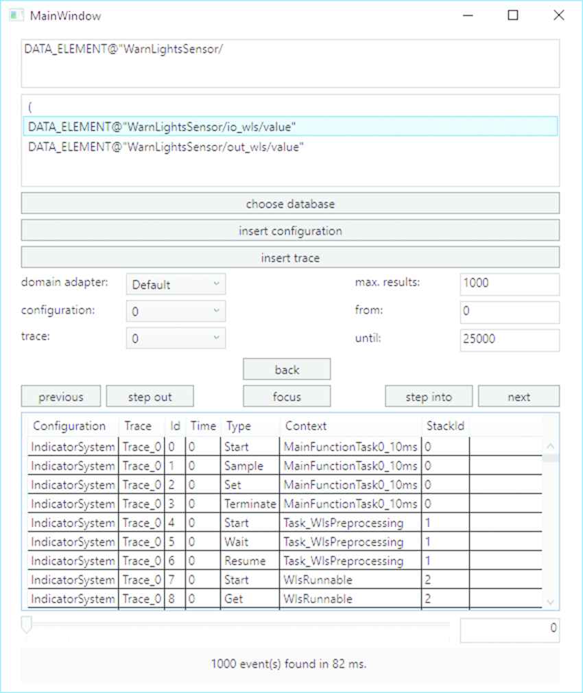
Prototype of a graphical frontend for architectural runtime verification (ARV).
It provides autocomplete for the property input, which is especially helpful for users without LTL experience. Furthermore, the user can select the desired domain adapter, so elements can be referred to in a familiar way. For example, in the AUTOSAR domain, it is common to reference elements by their path. The autocomple feature is useful here as well.
Once a valid property has been entered, the RV monitor is synthesized. The user can then select a trace and have the verification performed. The results (if any) are presented as a table of runtime events that support the assumption, i.e., satisfy the property.
7. EVALUATION OF PERFORMANCE
Performance-wise, only two aspects have a significant influence: the monitor synthesis (see Section 5.4) and the actual database query. The time ARV requires to synthesize a monitor depends on the complexity of the inquiry, i.e., the LTL expression. However, we found that it is almost negligible compared to the time needed to process the monitor. Even on modest laptops, it hardly exceeded 500ms with any of our example assumptions.
This is why the main focus for our performance analysis is regarding the execution of the monitor. We again used the example presented in Section 3. The SQLite database was filled with three 12s traces of a simulation. On a Haswel-based workstation PC, the monitor evaluates Listing 1 in about 38s and uses about one gigabyte of RAM. The high RAM utilization comes from a limitation of the implementation, which results in some parts of the query not being performed on the database, but locally. This in turn requires intermediate results to be cached (see the previous section). It could be solved by implementing those parts that rely on LINQ features not supported by EF in a different way or by a redesign of the data model. The latter is considered future work, because we consider it more feasible.
In order to evaluate ARV on a mobile device, we relied on .NET core and Xamarin.13 Unfortunately, the same monitor that works well with EF for .NET framework did not work with EF core. We tried different approaches to synthesize the LINQ, but were either faced with runtime exceptions caused by known issues in EF core14 or long run times. To be fair it must be said that at the time of this evaluation (mid 2019) EF core was still quite new and had known limitations. We expect that the situation has improved since then.
Nevertheless, we wanted to find out how the core idea of ARV to shift the processing to the database using composed queries compares to an FSM-based approach that processes every event on the client. Therefore, we conducted a small case study and im plemented another test application that verifies A3 in two ways: (1) using a (hand-crafted) composed query and (2) by using a “linear” query that implements an FSM. Both have been realized directly in C# using .NET core, so no synthesis is involved on our side. The FSM has been implemented using switch case statements in a for loop over every event and can be seen in Figure 9.
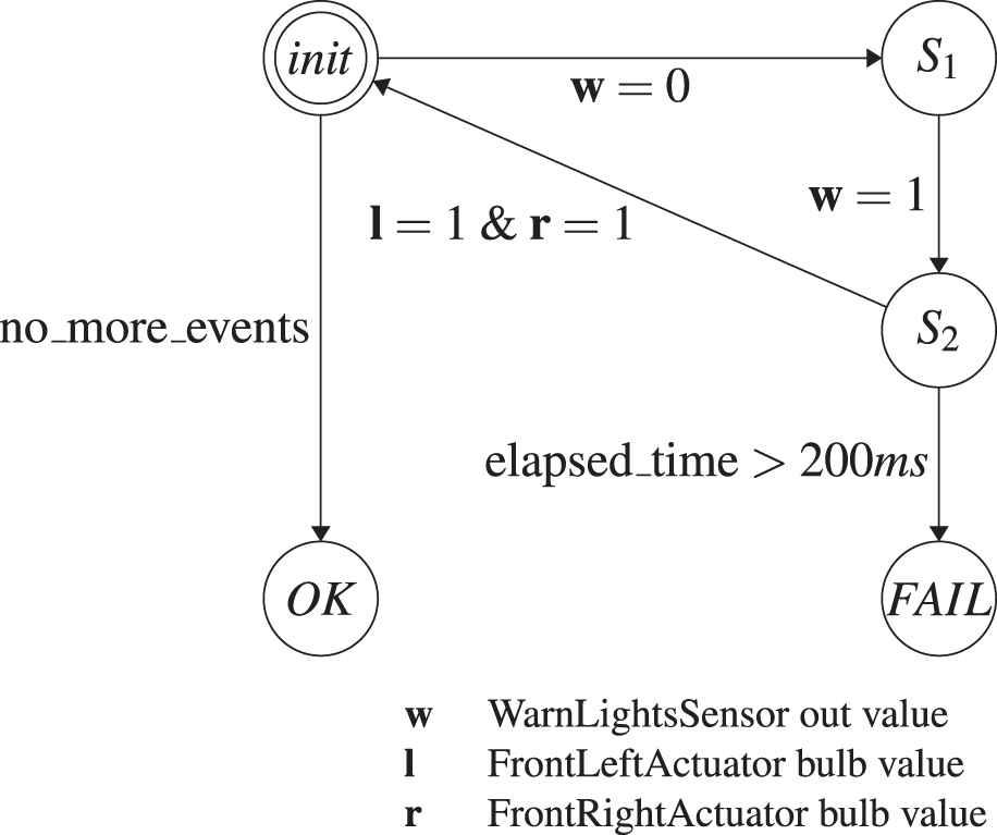
State machine to verify assumption A3.
We furthermore deactivated EF's change tracking. It is not needed as we were not making any changes to the database, but it had a significant negative performance impact on the linear query. Also, the composed query was designed so that EF core generates one SQL query, which does not require intermediate results to be downloaded. In order to keep the implementation simple, we only used one trace instead of three.
We evaluated both approaches using different client devices and database hosts. For example, in one setup, we used a MariaDB database on top of Arch Linux hosted in a virtual machine. This setup allowed us to precisely measure the data that is transmitted from the client to the database. Also, we could granularly limit the network bandwidth, e.g., to simulate a cellular network.
We also wanted to see how both approaches perform on a remote data storage in the cloud. After all, this is how ARV is intended to be used (cf. Section 4.4). For this we used an Azure SQL (cloud) database and evaluated the implementations on workstation PCs, different Laptops and mobile devices.
Figure 10 shows a benchmark that was conducted using a commercial off-the-shelf SAMSUNG Galaxy Tab A, which was connected to the internet via WiFi. We varied the maximum Database Transaction Units (DTUs)15 and measured query times.
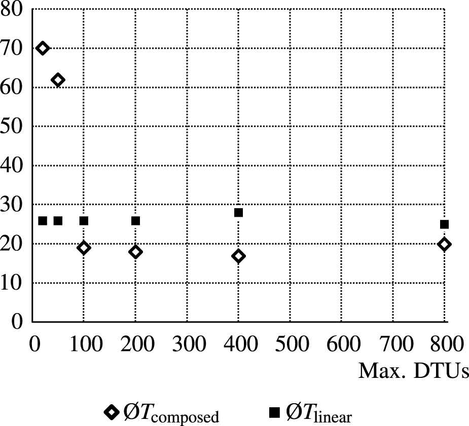
Varying cloud database performance.
It can be seen that the time required for the linear query Tlinear is unaffected by the DTU setting, staying at 26 seconds. In the Azure portal, we also observed that not all DTUs were used. The tablet, on the other hand, was at full load the whole time as far as we could measure. Thus, it seems that the CPU performance of the tablet was the limiting factor. We expected that the sequential processing of every event would occupy one CPU core. However, we observed that the other cores were busy, too. We attribute this to the garbage collection that kicked in frequently, because of the high RAM us age. Furthermore, we observed that downloading all data stalled the network connection on the tablet device. As expected, the high CPU and network load resulted in a high battery drain and the device got seemingly warm.
On the other hand, when performing the composed query, the tablet stayed mostly idle. EF core only transmitted the SQL and retrieved the result (as expected). This resulted in a very conservative use of RAM, CPU and network bandwidth. Meanwhile, The database peaked at the DTU limit. The most significant performance increase can be observed when changing from 50 to 100 DTUs. Here, the composed query outperforms the linear query. After that, the changes are negligible.
Generally, the composed query was heavy on the databases. When we hosted the DBMS ourselves, we observed that it strained at least one CPU core to 100% until the processing was completed. The reason that all databases struggle so much with the composed query is the same that was responsible for the problems described in the last section, i.e., there is no direct connection between related events of a value change. Currently, it requires an expensive self join, where every value event of a data element is joined with its successor. For example, the first finally expression in Listing 1 requires this to find the events where the warn light sensor value turns from 0 to 1. In the database, those events are not adjacent, but need to be queried explicitly.
Unfortunately, we cannot present every single result here. Most of them are very specific to the hardware used. However, overall the results were consistently showing that the linear query scales with the client hardware, i.e., CPU speed and RAM, whereas the composed query only depends on DBMS performance. This means that if the client is a modern PC and the network is fast, the linear query is much faster. If the client, however, is a mobile device, or the bandwidth is considerably reduced, the composed query outperforms the linear query.
To summarize, one can say that the approach of using composed queries instead of linear queries has its benefits. Especially, when the client is a battery powered mobile device operated in a bandwidth-limited environment. However, there is still room for improvement, which is discussed in Section 9.
8. RELATED WORK
We have investigated different RV approaches regarding their applicability to our requirements. They all follow the principles described in Section 2. Most approaches are thus primarily designed to be applied at runtime, as they employ a FSM for the verification, which ARV does not. Also, many approaches require that the architecture is enhanced with a dedicated centralized monitoring component, whereas ARV does not specify how the runtime information is collected. Nevertheless, approaches like RRF, LARVA or LOGSCOPE had a considerable influence on ARV's design.
8.1. MOP and MOPBox
One of the best known and most accepted approaches in the area of RV is the Monitoring Oriented Programming framework (MOP). Originally proposed in Ref. [29], MOP is not an implementation of RV, but instead a paradigm for establishing it as a generally applied means in software development. Therefore, MOP itself is independent of any programming or property specification language. In order to instantiate MOP in a specific domain, a language client is needed, e.g., JavaMOP for programs written in Java or BusMOP for PCI bus traffic. These language clients typically implement the instrumentation of the system under test and provide user interfaces and one could say that they consequently serve as (basic) domain-specific adapters. A wide range of logic plugins addresses the fact that property specification languages differ in their expressiveness and conciseness. Such a plugin would also be required to support real-time constraints, which is not available out of the box.
A generic implementation of this paradigm for JAVA is provided by MOPBox (see Ref. [30]). It follows a library-based approach with a simple API to define monitors as FSM which can be labeled with any kind of Java objects. Similar to MOP, MOPBox has no built-in support for real-time properties.
8.2. ASML
The first approach that considered RV at the level of software architecture was developed in 2001 by Mike Barnett and Wolfram Schulte at Microsoft Research (see Ref. [31]). It relies on a proxy component that receives every call from the client and forwards it to a model, which describes the intended behavior, as well as to the server. Both then execute concurrently. Before delivering the results of the server back to the client, the proxy checks whether the results coincide with those returned by the model. A violation of the (modeled) interface has been found if the results differ. The model is described in a dedicated architecture description language (ADL) named Abstract Machine Language (ASML).
Being one of the first approaches addressing this topic at all, its applicability is rather limited. It only supports specific client-server architectures. Thus, it would not be feasible to use it together with an AUTOSAR system. Also, it does not feature temporal relations of any kind.
8.3. DRACO
A second approach focusing on RV at the level of software architecture is named DistriNet Reliable and Adaptive COmponents (DRACO) and was presented by Vandewoude et al. in Ref. [32]. DRACO is a modular component RTE built as an extension of the SEESCOA Component Methodology (see Ref. [33]). The language used to specify the software architecture of a system under test is closely inspired by the Java programming language and the actual implementation of the component interaction is automatically generated in Java.
It addresses real-time systems by providing an optional central module to verify timing constraints, which can be attached to the connectors between components. It supports two different types of timing constraints. One is used to specify deadlines of messages, the other one explicitly addresses the periodicity of sending/receiving messages in embedded systems. Other temporal constraints are not supported. The constraints are verified by intercepting the sending/receiving of messages and forwarding such events to the central monitoring module.
Similar to ASML, DRACO is tied to its specific ADL. As this language is finally converted to Java, it cannot be easily applied for embedded systems, where C/C++ is still the dominant language (although there has been some progress in adopting Java in this domain).
8.4. RRF
The Runtime Reflection Framework (RRF) presented by Bauer et al. in Ref. [16] is similar to ARV in some aspects. It also aims at identifying misbehavior (and its causes) in distributed real-time systems. The framework explicitly supports real-time safety properties, which can be specified using a timed variant of LTL. Corresponding properties are then monitored with the help of timed automata.
A central idea of the approach is to decouple instrumentation and verification. This is achieved by introducing separate layers for logging events of the system under test and monitoring properties. It additionally includes a layer for diagnosing failure causes and a mitigation layer to recover from certain kinds of failures at runtime.
The potential distributed nature of a system under test is also taken into account in the design of this layered architecture. Logging and monitoring are performed locally for each component while diagnosis and mitigation are done centrally considering a holistic system view. The authors assume that usually only few components fail in a given system under test. Based on this assumption, they try to differentiate symptoms (e.g., wrong outputs) from actual failures by inferring a minimal subset of (probably) faulty components during diagnosis. In order to do so, they require to have a simple description of the system's behavior in terms of propositional formulas describing dependencies between correct input and output values within the system.
Bauer et al. validate their approach in Ref. [34] by explaining how to apply RRF to an AUTOSAR system. Here, for each existing component a dedicated AUTOSAR-compliant component for collecting logs and a monitoring component can be generated. Together with a corresponding diagnosis component, these components are then added to the architecture.
It appears that the (real-time) systems targeted by RRF are very similar to the ones targeted by ARV. However, there are differences in how RV is implemented. For example, in RRF it is performed locally with respect to a certain component in order to identify misbehavior, while the overall system architecture is first taken into account on the diagnosis layer. Hence, the monitoring aims at detecting faulty components. ARV in contrast focuses on misbehavior in the interaction of several components.
8.5. RV-BIP
In 2011, Falcone et al. presented RV of Behavior Integration Priority (BIP) systems (RV-BIP) in Ref. [35]. Their work is based on the BIP framework (see Ref. [36]), which provides an ADL to design (real-time) software architectures. The approach is not tied to a particular property specification language. Instead, Falcone et al. describe how to generally apply RV to component-based systems. In particular, they use an FSM that can be generated from any kind of LTL. Additionally, the authors introduce events based on atomic propositions that incorporate state information such as, e.g., the current value of a component's variable. These events are monitored by a generated monitoring component that is inserted into a given BIP software architecture and then connected to each other component.
The fact that the approach only works for BIP architectures makes it difficult to apply it to different domains. BIP architectures must be specified in terms of automata that include detailed behavioral information. Although BIP explicitly addresses the modeling of real-time systems, timing constraints can only be realized via a dedicated clock component.
8.6. LARVA
Originally, LARVA has been presented as an RV framework intended to instrument and monitor Java programs (online) [28]. It is based on timed automata that are specified in the underlying LARVA script language. Here, the system under test directly communicates with the monitor by emitting events.
In Ref. [24], Colombo et al. describe how to apply this approach offline in order to minimize the runtime overhead especially in the context of real-time systems. In offline mode, LARVA uses an event player to read a previously recorded log and emit the events to the monitor. LARVA uses a relational database to efficiently store a log. Regarding this aspect, LARVA was our main inspiration. However, in contrast to ARV, the approach stipulates that all relevant events are downloaded (via SQL select statements) and then passed to the monitor sequentially in chronological order.
8.7. LOGSCOPE
Barringer et al. follow a similar approach at NASA's Jet Propulsion Laboratory with LOGSCOPE in that they perform an offline RV based on logs [23]. This idea stems from traditional workflows at NASA, in which logs have been analyzed with the help of Python scripts written by the test engineers. The goal is mainly to ease test automation and debugging while producing only little runtime overhead.
They use an SQL database to store logs for one execution of the system under test. In order to support different types of logs, internally only an abstraction of a log is used while specific log formats can be supported with the help of corresponding log extractors. This idea influenced ARV's Domain Adapter concept.
LOGSCOPE also provides a property specification language for temporal patterns. These patterns have semantics similar to LTL and are automatically translated into parameterized automata. In contrast to LTL, patterns allow to easily specify ordered and unordered sequences of events. However, as stated earlier, the automata-based monitoring has its drawbacks, which is why ARV follows a different path.
The fact that the specification language is based on Python allows it to use any Python methods and libraries combined with custom Python predicates, which is a big advantage of LOGSCOP.
8.8. COPILOT
Pike et al. present an approach in Ref. [37] which is designed for monitoring periodically-scheduled hard real-time systems (online). They introduce the real-time guiding principles FaCTS, which state that any monitoring approach targeting real-time systems should neither change the functionality, certifiability, timing, nor SWaP (size, weight, and power) tolerances of the system under test. In order to follow these guidelines, they propose a sampling-based monitoring strategy as opposed to all approaches mentioned so far.
In general, sampling-based monitoring may lead to false results as values may be missed or sampled multiple times. The authors argue that for hard real-time systems, sampling is still suitable if the monitor and the monitored program are synchronized.
The monitor is specified in terms of streams (sequences) of state variables that shall be monitored using a language called COPILOT, which is embedded into Haskell. Monitors written in COPILOT are compiled into C programs that implement a state machine. The underlying COPILOT language is very powerful. It basically allows to implement any kind of logic by the use of custom operators and libraries.
It must be noted that ARV can also work with sampled data as it does not mandate, how the traces are captured. However, considering the argumentation of the authors themselves, there are caveats: (1) Even if monitor and monitored program are perfectly synchronized, sampling is only possible for periodic events (e.g., recurring value accesses) and (2) it is not possible to guarantee that any asynchronous event can be recorded. Thus, it could have an impact on reliability.
8.9. ENFORCER
Cotard et al. propose a service called ENFORCER that implements RV for AUTOSAR systems [17]. In particular, ENFORCER aims at the detection of mis-behavior in communication patterns involving different OS tasks. In this approach, the first step is to describe the expected system behavior by the means of state machines that react to certain system events.
Properties are specified in LTL and in the second step translated into state machines. The resulting automata yield the final monitor. In order to explicitly address the FaCTS principles introduced along with COPILOT, instrumentation and monitoring are performed inside a modified Real-Time OS (RTOS) kernel as this generates little runtime overhead and bypasses the scheduler.
As the monitor resides inside the kernel, it cannot inspect communication outside the realms of the OS. An example is the communication inside the AUTOSAR Virtual Functional Bus.
ENFORCER has been implemented in the kernel of an AUTOSAR-compliant open-source RTOS named Trampoline [38]. It can be configured using the OSEK Implementation Language (OIL), which has been extended by Cotard et al., so that it allows to define the required events, automata and properties.
9. CONCLUSION AND FUTURE WORK
This paper contributes a refined presentation of ARV—a new way of using RV on architecture level. It consists of a methodology and framework that enables a user to verify assumptions about the runtime behavior of component-based architectures by using a language based on an extended LTL. The goal is to help developers in the role of integrators to verify/refute hypotheses about misbehavior. The assumptions can be formulated “beyond model boundary,” as the underlying model is domain-independent. New architecture models can be integrated with the help of the Domain Adapter concept. Another advantage is that properties are translated into compendious database queries. Thus, in contrast to other RV approaches, where the client needs to process every individual runtime event, ARV allows to offload the processing to a standard database. Through the use of EF, it supports multiple DBMS.
We evaluated ARV using an AUTOSAR system. A prototype with a graphical interface enables a user to verify arbitrary hypotheses concerning the runtime behavior at architecture level. We furthermore evaluated the performance of the core concept of ARV against the traditional approach using FSM. For this, we benchmarked the composed query of a complex property against its “linear” counterpart, where every single event is processed on the client. We have found that ARV's approach generally fulfills the requirement to offload the main processing work to the database and therefore performs better on mobile devices.
Still, there is room for improvement. The evaluation has shown that our data model combined with the underlying technologies (EF, relational databases) is not ideal and may lead to complex queries that yield high memory usage and CPU load on both, the client and the database server. One reason is that there is no direct connection between the events of value changes in the model. We believe that a “shortcut,” which connects two value events of the same data element would greatly improve the query performance and reduce the overall query complexity. First experiments with an improved model have already been conducted and show a significant decrease in query time (order of magnitude). This is especially apparent when verifying assumptions over several configurations or traces.
Another aspect is the underlying database access. EF and relational databases might not be the best solution for ARV. It might be better to use other database technologies and paradigms that are more suited to runtime data and its relation to the architecture (e.g., graph and time-series databases).
Another aspect is the query language. Even with the autocomplete feature, our LTL variant is still quite cumbersome to use in a productive environment. Other languages, e.g., those used to query graphs or a custom domain-specific language might be more suitable to express typical assumptions regarding the runtime of integrated architectures. Work on this subject has already begun.
Finally, we want to further evaluate the universality of ARV and its capabilities. Therefore, we want to apply the approach to an actual heterogeneous system in the aerospace domain.
CONFLICTS OF INTEREST
There is no conflict of interest.
AUTHORS' CONTRIBUTIONS
Lars Stockmann wrote the majority of the article. He performed the experiments in the performance evaluation section and supervised Sven Laux, who designed the models, did the majority of the research and implemented the prototype as part of his master thesis. Both authors worked out the main concept presented in the paper. Professor Eric Bodden supervised the project as a whole, contributed the name of the framework, provided information about runtime verification and contributed valuable reviews.
Footnotes
We have changed the term “hypothesis” from the initial publication to “assumption,” because it has lead to some confusion
SystemDesk: www.dspace.com/go/systemdesk
AUTomotive Open System ARchitecture: www.autosar.org
VEOS: www.dspace.com/go/veos
ANTLR website: www.antlr.org
Entity Framework website: www.asp.net/entity-framework
SQLite website: www.sqlite.org
MariaDB website: www.mariadb.org/about
Azure SQL Database: www.azure.microsoft.com/services/sql-database
WPF introduction: https://docs.microsoft.com/visualstudio/designers/introduction-to-wpf
Xamarin website: www.xamarin.com
Entity Framework GitHub Issue 11900: Query source has already been associated with an expression (https://github.com/aspnet/EntityFrameworkCore/issues/11900)
Microsoft's definition of Database Transaction Units (DTUs): https://docs.microsoft.com/azure/sql-database/sql-database-purchase-models#dtu-based-purchasing-model
REFERENCES
Cite This Article
TY  - JOUR
AU  - Lars Stockmann
AU  - Sven Laux
AU  - Eric Bodden
PY  - 2021
DA  - 2021/02/16
TI  - Using Architectural Runtime Verification for Offline Data Analysis
JO  - Journal of Automotive Software Engineering
SP  - 1
EP  - 14
VL  - 2
IS  - 1
SN  - 2589-2258
UR  - https://doi.org/10.2991/jase.d.210205.001
DO  - https://doi.org/10.2991/jase.d.210205.001
ID  - Stockmann2021
ER  -


